Also Atari's Asteroids ist ein absoluter Klassiker. Dasselbe kann man von Battlezone und Tempest sagen, aber die anderen Atari Vektorspiele sind auch geil (kann es sein, dass Major Havoc das erste Videospiel mit (verstecktem) Minispiel ist?)
Folgendes Problem: Man kriegt für alle Chips Ersatz. Für alle? Nein, ein paar weigern sich, ach was erzähl ich? Also die 74LS170 dürften etwas schwer zu bekommen sein. Für den State-Machine-ROM muss man einen Adapter bauen und einen schnellen EEPROM nehmen. Für die alten ROMs muss man Adapter bauen, weil man keine so kleinen ROMs mehr bekommt, aber zumindest die 3 Spiele-ROMs kann man dann durch einen ersetzen. Die RAMs bekommt man nur noch NOS, aber die 4 2114 vom Vektor-CPU-RAM kann man durch einen 6116 ersetzen (und entsprechend durch einen 8k-SRAM, die werden noch hergestellt).
Nur den AD561 DAC, den kriegt man nicht mehr. Und wenn der doch mal auf eBay auftaucht, zahlt man übertriebene Preise für NOS-Chips, die mit etwas Glück noch 20 Jahre funktionieren.
Also dachte ich mir, mal gucken, was Analog Devices vergleichbares im Sortiment hat und bin auf den AD7533JNZ gestoßen. Ob das JNZ irgendwas macht, weiß ich nicht.
Der 7533 ist leider nicht ganz kompatibel und leider bin ich kein Elektroingenieur und kenne mich nicht so gut aus.
Ich habe es nicht hingekriegt, dass der 7533 einen bipolaren Output hat, d.h. das Signal um die 0-Linie herum auslenkt. Das Signal schlägt leider nur zu einer Richtung hin aus, ist also um den halben Bildschirm verschoben.
Versuche, dies zu korrigieren durch andere Wahl der Eingangsparameter führten zu einem total verzerrten und unbrauchbaren Bild, welches noch nicht einmal die Anforderung, sowohl positiv als auch negativ auszulenken, erfüllte.
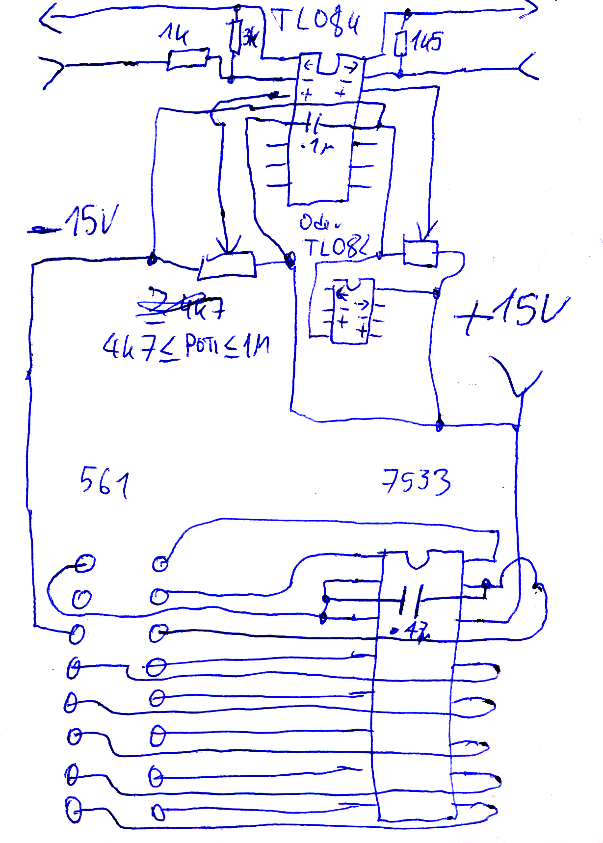
Daher wird zusätzlich zu dem AD7533 noch ein TL082 oder TL084 gebraucht.
Vorbereitung:
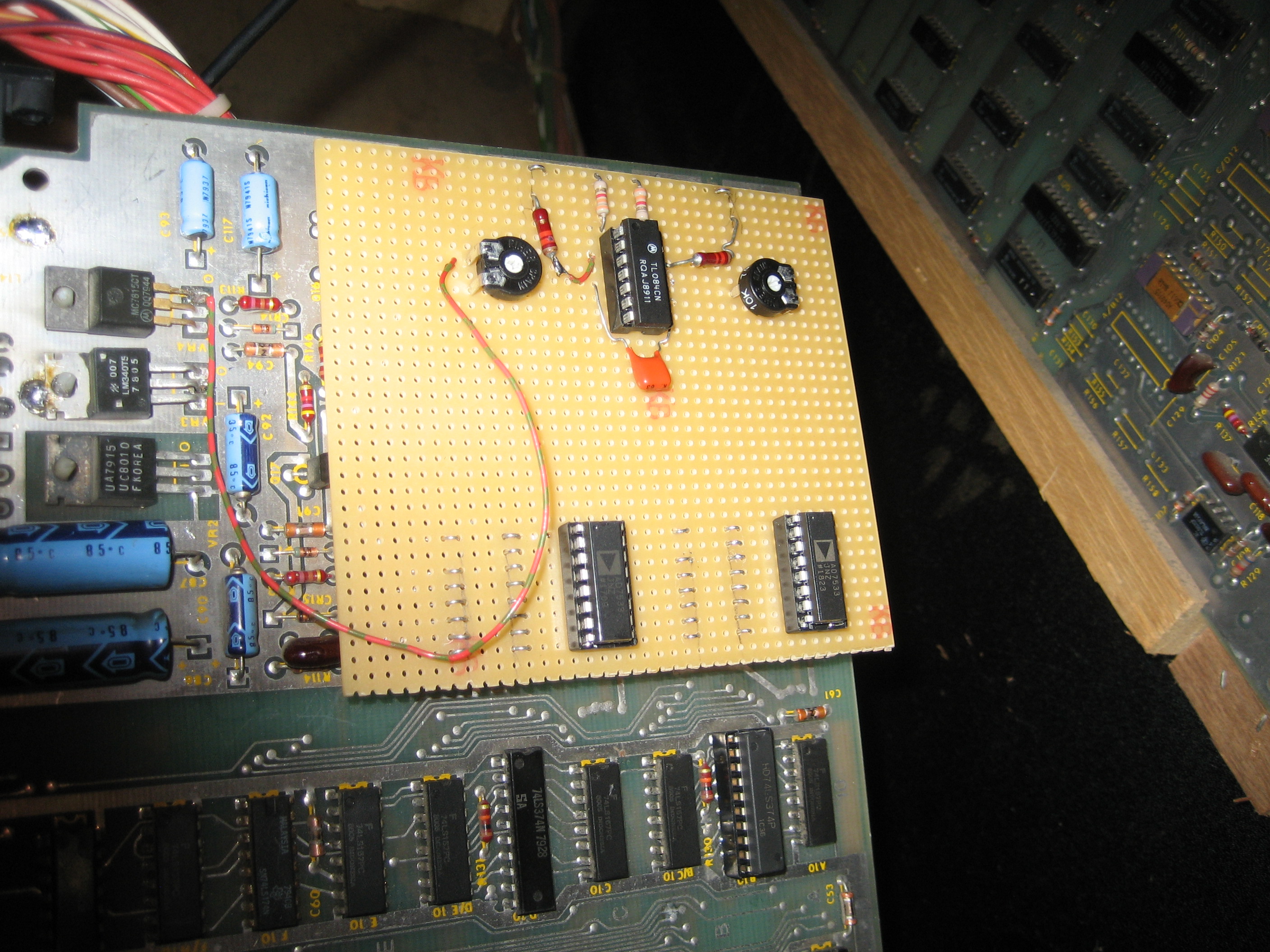
Erst einmal sind die beiden Original-DACs zu sockeln. Dann müssen die beiden Test-Abgriffe für X und Y, die sich jeweils direkt neben den Potis für die Bildgröße befinden, entfernt werden. Vorsicht beim Auslöten, wenn die nicht genau im 90° Winkel entfernt werden, beschädigen sie die Lötaugen.
Ich habe eine Platine genommen und alte abgetrennte Beinchen von Widerständen (und ich habe mich selbst für verrückt gehalten, die zu sammeln) an der richtigen Stelle eingelötet und umgebogen sowie in Chipockel gesteckt, damit man die Platine einfach einstecken und entfernen kann. Klar kann man die Adapterplatine auch permanent einlöten - aber was wenn einer von den TLs oder 4066er kaputt geht?
In beide Kontakte der X- und Y- Abgriffe (also 4 Kontakte) müssen ebenfalls Steckvorrichtungen gelötet werden - aus dem unteren kommt das Signal, der obere (zur Platinenkante zeigend) führt zum Monitor.
Ärgerlicherweise braucht der 7533 +15V. Der TL082 / TL084 auch. Diese Spannung ist aber nicht unter den Versorgungsspannungen des 561. Also muss ein Kabel vom Ausgang des 7815 (das ist der oberste Pin, also der, der der Platinenkante am Nahesten ist) zu der Adapterplatine geführt werden.
Verdrahtung:
| AD561 Pin | AD7533 Pin |
| 15 | 1 |
| 1 | 2 |
| 1 | 3 (Pin 2+3) : GND |
| 13 | 4 |
| 12 | 5 |
| 11 | 6 |
| 10 | 7 |
| 9 | 8 |
| 8 | 9 |
| 7 | 10 |
| 6 | 11 |
| 5 | 12 |
| 4 | 13 |
| EXT. +15V | 14 |
| 14 | 15 : +5V |
| 16 | 16 |
Das nun erzeugte Signal muss durch diesen komischen Schaltkreis durch. Es direkt zum Endverstärker und zum Monitor zu lenken, hatte ein krass verzerrtes Bild zur Folge.
Wir haben nun ein um den halben Bildschirm verschobenes Bild, das außerdem selbst voll aufgedreht den Bildschirm nicht ausfüt. Dies könnte man theoretisch mit den Op-Amps onboard korrigieren aber rate mal was - wenn ich es versuche, ist das Bild wieder total verzerrt!
Also was tun? Noch einen TL082 / TL084 nehmen und das Bild damit verstärken und bei der Gelegenheit noch verschieben, damit es wieder in Bildmitte ist.
Und so geht's: Erstmal brauchen wir für jeden Kanal ein Poti, das von +15V nach -15V gespannt wird. Der variable Abgriff wird dem positiven Eingang des Op-Amps zugeführt.
Der Ausgang vom Board (unterer Pin) kommt über einen 1k-Widerstand in den negativen Eingang des Op-Amps, dessen Ausgang mit einem Widerstand auf den negativen Eingang zurückgekoppelt ist.
Verdrahtung X-Achse:
Ausgang zum Monitor->TL082/TL084 Pin 1->3k Widerstand->TL082/TL084 Pin 2.
Signalausgang Mainboard->1k Widerstand->TL082/TL084 Pin 2
Ausgang Poti X->TL082/TL084 Pin 3.
-15V -> TL082/TL084 Pin 4.
Verdrahtung Y-Achse:
Ausgang zum Monitor->TL082 Pin 7 /TL084 Pin 16->1,5k Widerstand (1,2k..2k)->TL082 Pin 6/TL084 Pin 15.
Signalausgang Mainboard->1k Widerstand->TL082 Pin 5/TL084 Pin 2
Ausgang Poti Y->TL082/TL084 Pin 14.
+15V -> TL082 Pin 8/TL084 Pin 13.
(ich hoffe ich habe das richtig. Das Handgekrakel ist jedenfalls korrekt - Wenn mein Physiklehrer das sieht: Hey, wenn eine Leitung bis zu einem Pin geht, aber dann so ganz kurz davor aufhört oder knapp vorbei geht, gilt das als verbunden - ein Kabel, das nirgendwo hin geht, in einen Schaltplan einzuzeichnen, macht keinen Sinn!)

Well Atari's Asteroids can be considered a huge hit in the arcades and is now a classic. Same goes for Battlezone and Tempest and all the other Atari vector games are great as well (could it be Major Havoc is the world's first game with a (hidden) minigame?)
Now here's the problem: You can still buy all the chips new, except for a few and if they die, it's Game Over. Or is it? Well the 74LS170 could be hard to get, you need to make an adapter for the vector CPU state machine ROM for a fast EEPROM, the game's ROMs could be replaced with larger ones that are still being manufactured (only wasting 2k on the game ROMs which can be replaced by just a single 27C64), the 2114 SRAMs can still be had NOS, but you can rather easily replace the four vector RAMs with a single 6116 and of course you could buy a brand new 8k SRAM chip to replace it if you like to waste 6k of RAM (I don't).
Only the AD561 DAC chip is hard to get. If they even pop up on eBay, they demand outrageous prices and then they're NOS and you can be happy if they last 20 years.
So I thought let's see what Analog Devices has in stock that is still being made as of 2019 and see if I can get it to work in an Asteroids. No spoilers here, you already scrolled past the pictures, I succeeded (99%). The answer is the AD7533JNZ (no clue what the JNZ does and if a different chip like the JNL does it any different.)
But there is a problem: I'm no electronics engineer and didn't succeed in giving the 7533 a bipolar output. Instead the signal only deflects one direction on the axis instead of centering around 0V. The result is a picture that's shifted half the screen. Also, the signal's a little too weak to fill the screen even with the size pots all maxed out.
I sure tried to do it, but everything I tried resulted in a distorted picture, rendering the game (nearly) unplayable.
So, to fix this, I threw in another Op-Amp - a TL082 does just fine as does a TL084. And you can still get them new!
Preparation:
First you have to remove the original DACs and put sockets in their place if there aren't any yet. You'll also have to remove the X- and Y-Axis test clips - these actually serve as jumper wires, so when they're removed, the signals won't reach the monitor anymore and we can intercept them, manipulate them and send these signals to the monitor.
Also, the TL082/084 and the AD7533 need +15V which aren't available on the AD561's pins, so we'll have to lay a wire from the output of the 7815 (the one nearest to the edge of the board) to the adapter board we're going to build.
So we take a perfboard and solder wires so that they will match the two AD561 sockets as well as the X- and Y-Axis test clips. For this I used wire clippings from resistors and capacitors (and I called myself crazy for keeping the clippings). The pins are bent to do a 180° back to the solder side so they can be plugged in and pulled out without tearing off. I put them in another chip socket to make them easier to plug and unplug (since the prototype board often needed that). Also if any of the ICs below the adapter board breaks, it's better if you can just unplug it.
Take note that of the Test clips you removed, the upper one next to the board edge connects to the monitor while the lower one carries the signal output from the board's op-amp.
Wiring:
How the 7533 is to be wired up can be gathered from the table in the German section. You shouldn't have trouble reading the numbers.
Just remember to put a blocking capacitor between GND (Pins 2+3) and +5V (Pin 15) of the 7533. These usually have 0.1µF, which works quite well (if you omit the cap, the lines will end up squiggly) but the lines aren't perfectly smooth yet, but you'll barely notice it and you're probably happy that you can play the game and not have to throw away the board. Feel free to try different values of capacitors, like 0.2µF or 0.47µF or put an electrolytic 1µF in parallel with a 0.1µF deblocking one. Or just get the 5V from the +15V by putting a 78L05 right next to the DAC (and even here you'll need deblocking caps). Or a 5.1V Zener diode. Whatever. I haven't tried any of that.
Ah right - the circuitry for the Y-Axis is identical, so you can just do it again with the other axis.
Btw. the pictures are pretty large. You can right-click them, select show image and enjoy full size. I'm lazy.
So now we have an analog signal but it's not quite right yet. It needs centering around zero Volts and also some amplification to fill up the screen. For this we'll need a TL082 or if unavailable, a TL084.
To shift the signal, we'll need an adjustable voltage, so for each axis we put a potentiometer between -15V and +15V and route its output to the positive input of the axis' op-amp. The negative input arrives from the mainboard through a 1k resistor and the op-amp's output is fed back into the negative input through a resistor, 3k3 for Y, 1k5 for X. Or thereabouts. You can go like +-50% on these values.
Wiring X-Axis:
Output to monitor->TL082/TL084 Pin 1->3k Resistor->TL082/TL084 Pin 2.
Signal from mainboard->1k Resistor->TL082/TL084 Pin 2
Output pot X->TL082/TL084 Pin 3.
-15V -> TL082/TL084 Pin 4.
Wiring Y-Axis:
Output to Monitor->TL082 Pin 7 /TL084 Pin 16->1.5k Resistor (1.2k .. 2k)->TL082 Pin 6/TL084 Pin 15.
Signal from Mainboard->1k Resistor->TL082 Pin 5/TL084 Pin 2
Output pot Y->TL082/TL084 Pin 14.
+15V -> TL082 Pin 8/TL084 Pin 13.
Don't know if I got that right, but the doodle schematics are correct.